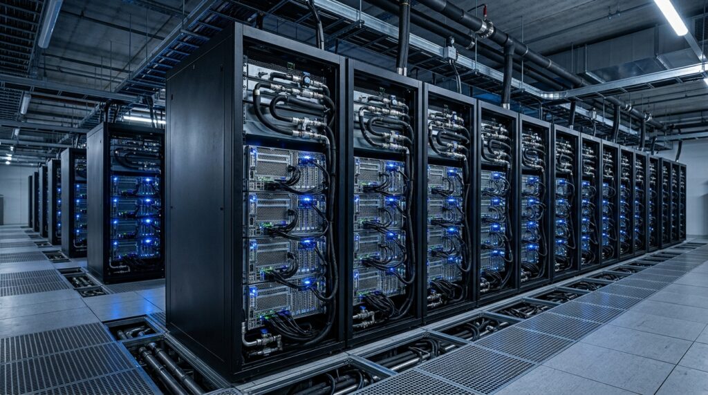
Mastering AI Data Center Rack Design and server cluster scalability isn’t just a matter of buying more hardware.
Scaling infrastructure from a single AI server to a multi-node cluster isn’t just a matter of buying more hardware. It is a highly complex engineering challenge involving power distribution, thermal management, and backend network fabrics.
This deep-dive report is tailored specifically for Chief Operating Officers (COOs), Chief Technology Officers (CTOs), and Lead Infrastructure Engineers—providing the exact insights needed to make smart investment decisions, mitigate operational risks, and optimize actual TCO in the age of accelerated computing.
Quick Summary: Three Core Truths Before You Buy
If you only have 60 seconds, here are the non-negotiable decisions you need to understand:
- Power Distribution: Do not attempt to run traditional AC power to high-density GPU racks. The OCP ORV3 standard utilizing 48V DC busbars is mandatory to sustain power loads above 40 kW without melting your cabling infrastructure.
- Thermal Management: Air cooling has hit a hard physical limit. Modern chips (like NVIDIA Blackwell) strictly require Direct Liquid Cooling (DLC) paired with a 25% Propylene Glycol (PG25) fluid mixture.
- Backend Fabric: InfiniBand delivers the absolute highest performance but locks you into a single proprietary ecosystem. RoCEv2 (via Spectrum-X) offers a more economical, open alternative, but requires an operations team with top-tier network tuning expertise to guarantee lossless behavior.
1. AI Data Center Rack Design: Power Density and the Shift to OCP ORV3 48V DC
Modern GPU racks built for training and inferencing Large Language Models (LLMs) demand anywhere from 40 kW to over 130 kW per rack—shattering the 5 kW–15 kW limits of traditional data center infrastructure.
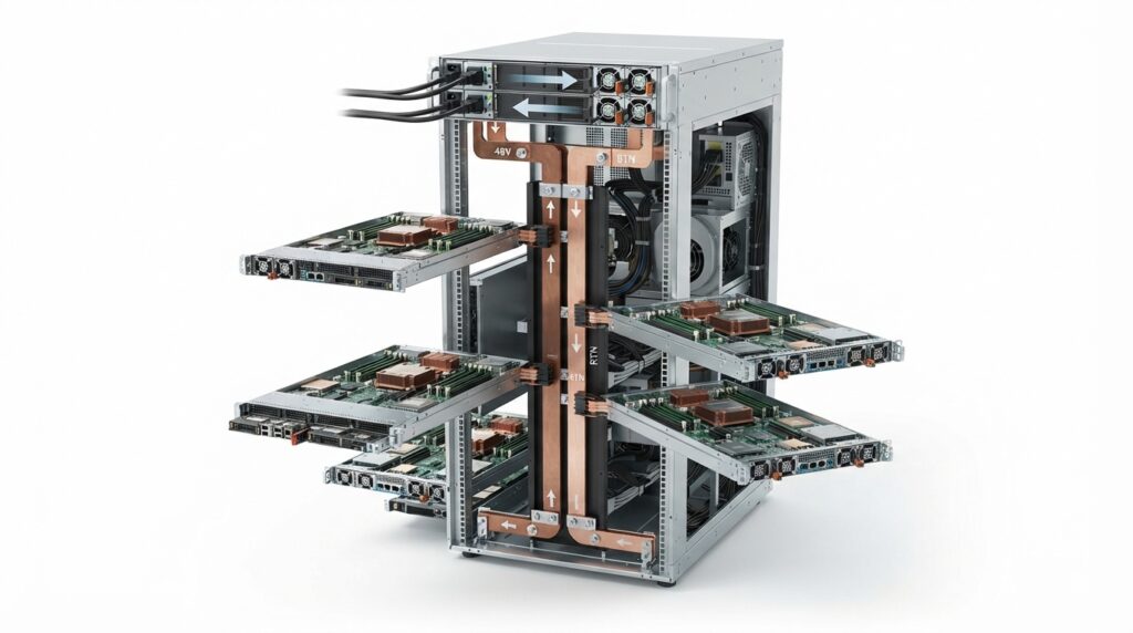
A Comparison of Common AI Rack Configurations
| Rack Configuration | Total Power | GPU Type | System Density | Weight (Fully Loaded) | Cooling Method |
| Legacy A100 | 32 kW | NVIDIA A100 | 8 servers × 8 GPUs | < 500 kg | Air-Cooled |
| Legacy H100 | 34 kW | NVIDIA H100 | 6 servers × 8 GPUs | ~ 800 kg | Air-Cooled |
| GB200 NVL36 | 73 kW | Grace Blackwell | 9 servers × 4 GPUs | ~ 1,000 kg | Direct Liquid Cooling (DLC) |
| GB200 NVL72 | 132 kW | Grace Blackwell | 18 servers × 4 GPUs | ~ 1,400 kg | Direct Liquid Cooling (DLC) |
| Blackwell Ultra / Rubin | 250 kW–900 kW | Next-Gen | Up to 576 GPUs | > 2,200 kg | High-Density Liquid |
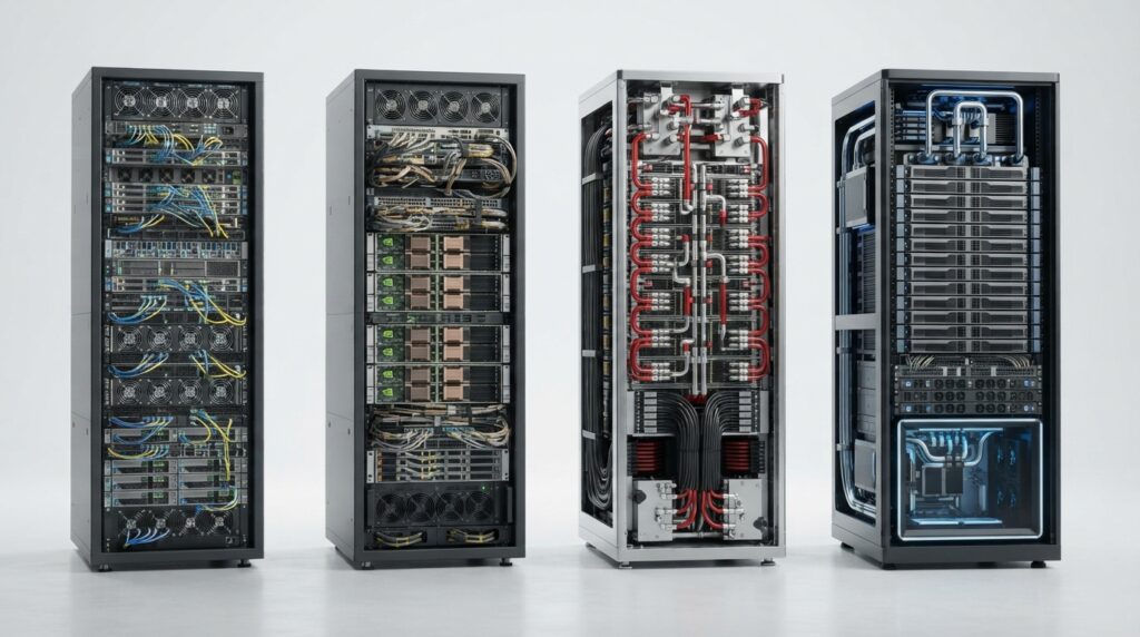
Why OCP ORV3 48V DC Architecture Is Non-Negotiable
Routing traditional AC power directly to individual servers at scales exceeding 100 kW introduces massive transmission losses and requires copper cables so thick they physically block vital airflow. The Open Rack V3 (ORV3) standard solves this bottleneck by:
- Centralizing Power Conversion: Consolidating 3-phase AC utility power into a single centralized Power Shelf within the rack to convert it to a unified DC voltage (48V–54V).
- Solid Copper Busbars: Distributing that DC power along a vertical busbar at the rear of the rack. Server sleds simply blind-mate directly into the busbar, completely eliminating bulky power cables.
Editor’s Take: If your facility is bottlenecked by floor weight capacity or power availability, your best move is density spacing. Limit your deployment to a maximum of four 8-GPU server nodes per rack to keep power consumption under 50 kW. This allows you to leverage existing infrastructure instead of spending $200,000 to $300,000 per rack footprint to retrofit the facility.
2. Thermal Management: The Physics Behind Secondary Loop (TCS) Coolant Selection
Once the thermal design power (TDP) of AI processors crosses the 1,000W-per-chip threshold, air cooling fails completely due to the physical limits of air’s heat capacity. Direct Liquid Cooling (DLC)—which routes fluid straight to the processor surface via microchannel cold plates—is mandatory to prevent devastating thermal throttling.
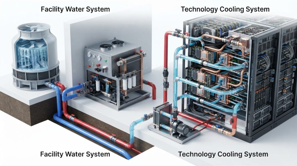
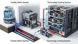
The Isolated Two-Loop Architecture
A standard enterprise liquid cooling deployment isolates fluids into two distinct closed loops to ensure mechanical safety and chemical control:
- Primary Loop (FWS – Facility Water System): Routes industrial facility water from outdoor cooling towers, dry coolers, or chillers into the data center white space.
- Secondary Loop (TCS – Technology Cooling System): Circulates high-purity fluid directly through the manifolds, quick-connects, and cold plates on the GPUs. A Coolant Distribution Unit (CDU) acts as the “heart” of the system, exchanging heat between the two loops via a brazed plate heat exchanger without ever mixing the fluids.
Coolant Choice: PG25 vs. Deionized (DI) Water
While Deionized (DI) water offers superior heat transfer performance, it is highly prone to biological growth that clogs cold plate microchannels, and it poses a severe freezing hazard during transport. Consequently, ASHRAE guidelines recommend a 25% Propylene Glycol (PG25) mixture packed with corrosion inhibitors.
However, opting for PG25 introduces a massive engineering trade-off that decision-makers must account for in their operating budgets:
$$Q = \dot{m} \cdot C_p \cdot \Delta T$$
Because PG25 features a lower specific heat capacity ($C_p \approx 3.85 \text{ kJ/kg}\cdot\text{K}$, roughly 8% lower than pure water) and its dynamic viscosity is 2.5 times higher at 20°C, the system demands:
- A 15% to 20% increase in fluid volumetric flow rate ($\dot{m}$) to match pure water’s cooling efficiency (requiring a minimum design target of 1.8 L/min/kW).
- A 25% to 30% jump in CDU pump power consumption to overcome the increased frictional resistance within the piping.
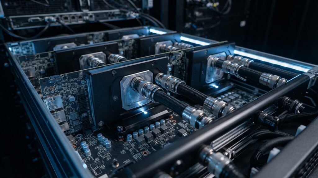
Piping and Cleanliness Standards
To ensure a system operating lifespan exceeding 25 years, enforce strict Lenovo Neptune clean design rules: restrict wetted metals exclusively to copper alloys and stainless steel. Completely ban carbon steel and traditional soldering to eliminate the risk of rust and flux residues leaching into the coolant loop. For infrastructure piping, prioritize advanced polymers like PP-H or PVDF joined via infrared heat fusion.
3. Backend Network Fabrics: InfiniBand vs. RoCEv2
An AI backend fabric operates under massive, synchronized compute loads. During distributed training, a single delayed or dropped packet stalls the entire GPU cluster. Therefore, the network must guarantee microsecond-level tail latency and strict lossless behavior.
High-Performance AI Network Fabrics Compared
| Technical Specifications | InfiniBand (NDR/XDR) | Standard RoCEv2 (Ethernet) | Spectrum-X (NVIDIA RoCEv2) |
| Lossless Mechanism | Hardware Credit-based | Complex PFC + ECN tuning | PFC/ECN + Dynamic Routing |
| Average Latency (p50) | 1–2 $\mu\text{s}$ | 2–5 $\mu\text{s}$ | 1.5–2.5 $\mu\text{s}$ |
| Effective Bandwidth (AllReduce) | Highest (~ 350 GB/s) | Fair (~ 270–290 GB/s) | Very High (~ 340–360 GB/s) |
| Fabric Routing | Static / Centralized Management | Static ECMP Routing | Hardware Adaptive Routing |
| Ecosystem | Closed (NVIDIA Dominated) | Open (Multi-vendor) | Partially Open (Requires SuperNIC) |
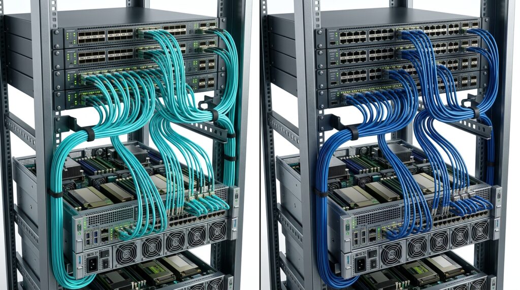
Rail-Optimized Stripe Architecture
To minimize network hops during collective communication algorithms like AllReduce, large-scale clusters are organized using a Rail-Optimized topology.
                 [ BACKBONE SWITCHING LAYER (SPINE SWITCH) ]
                              ▲                          ▲
                              │                          │
                 ┌────────────┴─────────────┐┌───────────┴────────────┐
                 │       RAIL 1 LEAF        ││       RAIL 2 LEAF      │
                 │     (Leaf Switch 1)      ││     (Leaf Switch 2)    │
                 └────────────▲─────────────┘└───────────▲────────────┘
                              │                          │
                              │  (Direct 1-Hop Connect)  │
                              │                          │
                 ┌────────────┴──────────────────────────┴────────────┐
                 │                AI SERVER NODE                      │
                 │   ┌────────────────────────────────────────────┐   │
                 │   │     [ GPU 1 ]                [ GPU 2 ]     │   │
                 │   └────────────────────────────────────────────┘   │
                 └────────────────────────────────────────────────────┘
In this architecture, GPU position #1 across every single server node connects directly to Leaf Switch 1, GPU position #2 connects to Leaf Switch 2, and so on. This ensures that AllReduce operations between identical GPU rails are handled entirely within a single switch hop at the leaf layer, preventing traffic from congesting the upper Spine switches.
To build a non-blocking fabric (1:1 oversubscription ratio), the maximum number of servers ($N_{\text{servers}}$) a single networking block—or “Stripe”—can support is determined by the leaf switch port count ($P$):
$$N_{\text{servers}} = \frac{P}{2}$$
Correspondingly, the maximum number of cluster GPUs supported within that single non-blocking Stripe is:
$$N_{\text{GPU}} = N_{\text{servers}} \cdot 8 = 4P$$
Real-World Application: Utilizing a standard 64-port switch ($P=64$), a single Stripe supports up to 32 servers and 256 GPUs in a perfectly non-blocking state. For LLM training models characterized by sparser communication profiles, you can implement a Rail-only architecture. Eliminating the spine switch layer entirely slashes networking CAPEX by 38% to 77% while fully meeting your workload’s data throughput requirements.
Editor’s Take: What Decision Makers Should Do Next
Buying AI compute without verifying your facility’s physical electromechanical limits is like dropping a jet engine into a stock sedan chassis. To secure your investment and avoid multi-million dollar operational failures, implement this roadmap immediately:
- If your priority is absolute maximum performance and speed-to-market: Deploy an OCP ORV3 unified rack footprint paired with an InfiniBand backend fabric. This combination delivers out-of-the-box lossless networking and factory-optimized liquid distribution manifolds. Your upfront CAPEX will be substantially higher, but you eliminate the operational risks of custom network configurations.
- If your priority is cost control and leveraging existing multi-vendor infrastructure: Choose a RoCEv2 Ethernet fabric paired with a Hybrid (Air + Rear-Door Heat Exchanger) cooling strategy. This approach allows you to keep rack power profiles under 50 kW, bypassing catastrophic floor-load retrofits and avoiding vendor lock-in. However, ensure your network engineering team is highly capable of configuring and validating complex PFC and ECN parameters to prevent fabric-wide congestion collapse.
Your Next Action Step: Before signing any purchase orders for GPU clusters, legally require your systems integrator to provide a detailed fluid-dynamics data sheet for the TCS loop and a localized weight-distribution plot per square foot of your raised floor. If a vendor cannot or will not produce these engineering specs, freeze the procurement until an independent infrastructure audit can be performed.
## Deepen Your Enterprise AI Infrastructure Roadmap
Scaling out multi-node compute clusters requires absolute alignment across your hardware footprint, silicon architecture, and data engineering layers. Complete your data center blueprint with our hands-on technical deep dives:
- Silicon & Accelerator Selection: Compare the raw compute performance, memory walls, and multi-chiplet layouts of next-gen processors in [Enterprise AI Server Hardware Guide: GPU, Storage & Networking].
- Hardware Form Factors: Learn how factory-integrated computing boxes compare directly against custom open-compute rack designs in [AI Appliance vs. Dedicated AI Server: Data Center Guide].
- Physical Deployment Blueprint: Discover the literal rack spacing rules, power distribution thresholds, and climate engineering steps required for on-premises clusters in [Zanus AI Hardware Architecture & Server Setup Guide].
- Financial TCO Calculation: Learn how shifting your distributed training from cloud OpEx to local CapEx completely eliminates recurring token fees over a 5-year cycle in [Zanus AI Pricing & ROI: The Real Cost of On-Premises AI].
- Data Sovereignty & Legal Guardrails: Are cloud-hosted data nodes exposing your organization to privacy lawsuits? Read our legal compliance audit in [How to Deploy Air-Gapped AI for HOA Property Management].
- Edge AI Commercial Automation: Explore how local processing arrays drive business efficiency by automating high-throughput computer vision workflows in [How to Automate HOA Property Inspections with Edge AI].
Open Compute Specifications: Official OCP Open Rack V3 (ORV3) Design Standards
Thermal Engineering Guidelines: ASHRAE Data Center Liquid Cooling Technical Committees
Lossless Networking Frameworks: NVIDIA Spectrum-X RoCEv2 Architecture Deployment Guide