
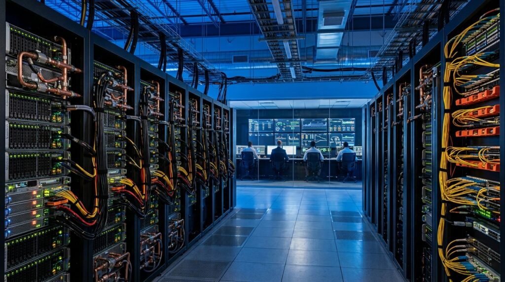
This comprehensive Enterprise AI Deployment Report addresses how the migration of artificial intelligence (AI) workloads from public cloud environments back to on-premises infrastructure is accelerating.
The migration of artificial intelligence (AI) workloads from public cloud environments back to on-premises infrastructure is accelerating. This shift is driven by a critical need for long-term cost optimization, data sovereignty, and compliance with increasingly stringent regulatory frameworks. Legal mandates like the European Union’s General Data Protection Regulation (GDPR), the Digital Operational Resilience Act (DORA) for financial systems, and the European Health Data Space (EHDS) enforce strict data residency and access controls. Consequently, over 71% of enterprise AI infrastructure is now leaning toward off-cloud environments.
However, establishing a high-performance AI computing cluster on-premises is fundamentally different from a traditional IT upgrade. It is a highly complex industrial engineering project. Success requires precise synchronization between advanced mechanical and electrical designs, lossless networking, and optimized software stacks.
For enterprise decision-makers evaluating multi-million-dollar infrastructure investments, this report cuts through the marketing hype to provide actionable engineering benchmarks, real-world timelines, and a rigorous go-live blueprint.
1. Technical Foundations & Physical Infrastructure Requirements
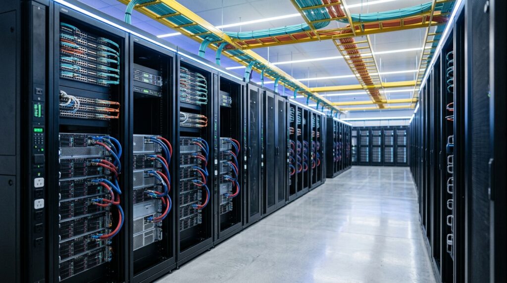
To plan an accurate deployment roadmap, engineering teams must evaluate the physical, thermodynamic, and electrical demands of modern high-performance computing clusters. Systems like the NVIDIA Hopper DGX H100/H200 and the Blackwell DGX B200 place unprecedented strains on standard data center designs.
Hardware Specification Breakdown
The table below contrasts the core engineering and physical specifications between the two dominant generations of enterprise AI hardware.
| Technical Specification | NVIDIA DGX H100 / H200 System | NVIDIA DGX B200 System |
| GPU Architecture | Hopper (GH100) | Blackwell |
| GPUs per System | 8x H100 / H200 Tensor Core | 8x Blackwell |
| Thermal Design Power (TDP) per GPU | Up to 700W (Air-Cooled) | Up to 1000W (Air) / 1200W (Liquid) |
| Maximum System Power Consumption | 10.2 kW | ≈14.3 kW |
| Physical Dimensions (H x W x D) | 356 × 482.3 × 897.1 mm (8 RU) | 444 × 482.2 × 897.1 mm (10 RU) |
| System Weight | 130.45 kg (287.6 lbs) | ≈158.7 kg (349.8 lbs) |
| Operating Temperature Threshold | 5°C – 30°C (41°F – 86°F) | 5°C – 30°C (41°F – 86°F) |
| Power Supply Unit (PSU) Redundancy | 4+2 Redundant (4 PSUs minimum) | 5+1 Redundant (3 PSUs minimum) |
| GPU Interconnect Bandwidth (NVLink) | Gen 4 (900 GB/s bidirectional) | Gen 5 (1.8 TB/s bidirectional) |
| System Memory (RAM) | 2 TB DDR5 | 2 TB (Configurable up to 4 TB) |
Deployment Decision Matrix: Which Platform Fits Your Organization?
| Scenario | Recommended Platform | Why |
|---|---|---|
| Existing enterprise data center with standard air cooling | DGX H100 / H200 | Minimizes facility upgrades while delivering strong AI training and inference performance. |
| New AI factory or greenfield deployment | DGX B200 | Designed for higher rack density, liquid cooling, and next-generation AI workloads. |
| Budget-constrained AI pilot | DGX H100 / H200 | Lower infrastructure costs and simpler operational requirements. |
| Large-scale foundation model training | DGX B200 | Higher memory bandwidth and compute density improve long-term scalability. |
Altitude Derating Analysis
Air-cooled AI infrastructure is highly sensitive to ambient air density. Data center temperature setpoints must be systematically derated based on altitude above sea level to prevent thermal damage:
- 0 to 1,000 meters (0 to 3,280 ft): Standard operating window allows ambient intake up to 30°C.
- 1,000 to 1,524 meters (3,280 to 5,000 ft): Maximum permissible intake temperature drops to 25°C.
- 1,524 to 3,048 meters (5,000 to 10,000 ft): Maximum intake temperature is strictly restricted to 20°C. Absolute operating altitude must not exceed 3,048 meters.
Editor’s Take: If your data center is located in a high-altitude region and your facilities team fails to adjust HVAC setpoints to compensate for lower air density, your hardware will experience chronic thermal throttling. This can secretly degrade your training and inference throughput by 20% to 40% without throwing explicit hardware failures.
2. Phased Project Roadmap (Weeks 1–24)
An on-premises AI deployment timeline varies significantly based on cooling architecture (air vs. liquid) and rack density. The following 5-phase schedule balances standard enterprise governance with the fast-paced deployment sprints required for production-ready AI clusters.
+---------------------------------------------------------------------------------------------------------+
|                               PROJECT TIMELINE & PHASED ROADMAP (WEEKS 1-24)                             |
+---------------------------------------------------------------------------------------------------------+
| Phase 1: Site Assessment & Facilities Procurement [Weeks 1-8]                                            |
| [Calculate power loads, finalize utility contracts, prepare physical floor space] ================>   |
+---------------------------------------------------------------------------------------------------------+
| Phase 2: Hardware Delivery & Mechanical/Electrical Integration [Weeks 9-14]                             |
| [Racking, phase balancing, deploy liquid-cooling CDU and piping plumbing]          ===============>     |
+---------------------------------------------------------------------------------------------------------+
| Phase 3: Network Fabric Construction & Parallel Storage Integration [Weeks 15-17]                       |
| [Run 400G/800G optics, manually configure PFC/ECN, validate GPUDirect Storage]         ===========>     |
+---------------------------------------------------------------------------------------------------------+
| Phase 4: Software Stack Uniformity, Orchestration & Stress Testing [Weeks 18-20]                        |
| [Align kernel drivers, deploy Kubernetes DRA, run Linpack & NCCL benchmarks]                 =====>     |
+---------------------------------------------------------------------------------------------------------+
| Phase 5: Cluster Optimization, Handover & Production Go-Live [Weeks 21-24]                               |
| [Establish Day-2 operations, automate checkpoint saves, complete operator training]             ==>     |
+---------------------------------------------------------------------------------------------------------+

Detailed Enterprise AI Deployment Report Phases
- Phase 1: Site Assessment & Facilities Procurement (Weeks 1 to 8)
- Electrical Assessment: Validate continuous power delivery capabilities. A cluster of 200 Blackwell B200 GPUs (25 nodes) draws a continuous compute load of approximately 350 kW. Facilities must implement online, double-conversion UPS systems configured for N+1 or 2N redundancy to isolate sensitive silicon from grid anomalies.
- Utility Grid Interconnection: This is often the single largest bottleneck in the project lifecycle. Grid connection approvals can take anywhere from 12 to 36 months depending on regional utility capacity. If your grid timeline cannot meet business goals, prioritize prefabricated modular data centers or established colocation facilities to bypass structural construction delays.
- Phase 2: Hardware Delivery & Mechanical/Electrical Integration (Weeks 9 to 14)
- Physical Racking: Mount systems into specialized deep enclosures. Because a single DGX H100 system weighs 130.45 kg (over 287 lbs), deployment teams must use mechanical server lifts and OSHA-compliant personal protective equipment (PPE) to eliminate injury and chassis warping risks.
- Liquid Cooling Plumbing: For liquid-cooled Blackwell configurations, engineers must integrate dedicated Coolant Distribution Units (CDUs). This involves running secondary loop manifolds carrying treated water (typically 40°C–45°C) directly to the direct-to-chip cold plates, followed by rigorous mechanical pressure testing to ensure zero leaks.
- Phase 3: Network Fabric Construction & Parallel Storage Integration (Weeks 15 to 17)
- Physical Fabric Deployment: Route high-speed optical cabling (400 Gbps or 800 Gbps) from server NICs to leaf and spine switches.
- Storage Fabric Coupling: Deploy NVMe-based parallel storage arrays supporting GPUDirect Storage (GDS). This bypasses the host CPU, allowing data to stream directly into GPU memory via DMA (Direct Memory Access), minimizing I/O latency during large batch processing.
- Phase 4: Software Stack Uniformity & Validation Testing (Weeks 18 to 20)
- Driver Alignment: Flash and lock a standardized operating system (such as Ubuntu or NVIDIA DGX OS). Ensure absolute version parity across the Linux kernel, NVIDIA proprietary drivers, and the CUDA toolkit (version 12.4+ is required for Blackwell features) across all compute nodes.
- Orchestration Deployment: Configure Kubernetes with Dynamic Resource Allocation (DRA). This allows infrastructure teams to fractionalize or pool physical GPUs across disparate data science teams without causing hardware resource contention.
- Phase 5: Optimization, Handover & Production Go-Live (Weeks 21 to 24)
- Validate the entire cluster using end-to-end LLM training workloads to isolate hardware infant mortality. Finalize Day-2 operations, monitoring dashboards, and runbooks before handing the infrastructure over to product engineering.
Deployment Timeline Benchmarks by Scale and Cooling Topology
| Cluster Scale | Air-Cooled Architecture (DGX H100 / H200 HGX) | Liquid-Cooled Architecture (GB200 NVL72) | Primary Schedule Drivers |
| Small to Mid (10–50 Racks) | 1 – 3 Weeks | 3 – 8 Weeks | Air cooling eliminates CDU installation, secondary loop plumbing, and fluid pressure testing, significantly accelerating mechanical setup. |
| Mid to Large (50–200 Racks) | 3 – 8 Weeks | 2 – 4 Months | Highly dependent on facility-level chilled water loops, Computer Room Air Handler (CRAH) capacity, and structural floor-loading limits. |
| Large-Scale (200–500 Racks) | 2 – 4 Months | 4 – 8 Months | Requires deep coordination among parallel mechanical, electrical, and plumbing (MEP) crews. Large-scale fluid loop leak testing is highly time-consuming. |
| Hyperscale (500+ Racks) | Phased Deployment (3–6 Months / Phase) | Phased Deployment (6–12 Months / Phase) | Projects must be segmented into electrically isolated failure domains to match regional substation power provisioning schedules. |
Operational Impact: If your timeline is aggressive and your staff lacks specialized plumbing expertise, select air-cooled configurations for deployments under 50 racks. Attempting to build an unmanaged liquid-cooling loop without vendor-led integration will easily double your timeline due to preventable pressure drops and micro-leak remediations.
3. Top 5 Fatal Mistakes in On-Premises AI Integration
Traditional data center frameworks fail when applied to modern AI infrastructure. Enterprise teams must avoid these five systemic mistakes during the planning and architectural phases.
Mistake 1: Underestimating Electrical and Thermal Power Realities
Traditional IT infrastructure planning assumes average server power draw and relies on standard air cooling. Applying these legacy calculations to high-density GPU nodes results in sudden thermal shutdowns, tripped circuit breakers, and long-term hardware degradation.
- The Underlying Engineering Failure: According to the first law of thermodynamics, all electrical energy delivered to a compute node is converted into heat. The engineering formula to calculate this thermal output is:$$\text{Thermal Output (BTU/hr)} = \text{Power Consumption (W)} \times 3.412$$A single Blackwell DGX B200 server operating at peak computational load draws 14.3 kW, generating a continuous thermal load of $14,300 \times 3.412 = 48,791.6\text{ BTU/hr}$.If a data center deploys a high-density configuration containing 4 DGX B200 nodes in a standard 42 RU cabinet, that single rack draws a massive 57.2 kW of electrical power. The resulting thermal output is $57,200 \times 3.412 = 195,166.4\text{ BTU/hr}$.To cool a 57.2 kW rack using traditional air-cooling methodologies, the required volumetric airflow is calculated using the industry baseline equation:$$\text{Required Airflow (CFM)} = \text{Power Consumption (kW)} \times 157$$$$\text{Required Airflow} = 57.2 \times 157 = 8,980.4\text{ CFM}$$Pushing nearly 9,000 CFM (Cubic Feet per Minute) of chilled air through a standard 19-inch rack footprint is physically impossible without exceeding safe acoustic exposure levels (>98.7 dB) and wasting extreme amounts of energy on high-velocity fan power.
- The Cascading Project Risk: When an air-cooled system reaches its thermodynamic limits, internal component sensors trigger thermal throttling, dropping GPU clock speeds to save the silicon. This drastically extends model training times beyond project deadlines. In a complete cooling failure, a 50 kW rack will experience catastrophic heat build-up in less than 10 seconds, causing permanent transistor degradation before the facility’s legacy backup cooling loops can respond.
Mistake 2: Network Fabric Misconfiguration and Lossless Ethernet Drift
In distributed AI training environments, overall cluster performance depends on the speed at which gradients are synchronized across hundreds of nodes via east-west network traffic, rather than individual GPU speed.
- The Underlying Engineering Failure: InfiniBand architectures utilize hardware-level, credit-based flow control to ensure a completely lossless network. Standard Ethernet, however, is built as a best-effort fabric that drops packets when switch buffers experience congestion.To execute Remote Direct Memory Access over Converged Ethernet (RoCEv2) with performance matching InfiniBand, network teams must precisely configure two distinct congestion management protocols:
- Priority Flow Control (PFC – IEEE 802.1Qbb): This stops buffer overflows by sending pause frames upstream to the transmitting NIC when a specific queue threshold is breached (typically mapping AI traffic exclusively to Class of Service/Priority 3).
- Explicit Congestion Notification (ECN – RFC 3168): This allows switches to mark packet headers when buffers near capacity. The receiving endpoint detects this mark and returns a Congestion Notification Packet (CNP), instructing the sender to reduce its transmission rate before packets are dropped. This mechanism is fine-tuned via the Data Center Quantized Congestion Notification (DCQCN) algorithm at the transport layer.
- The Cascading Project Risk: If your network team allows configuration drift or improperly calculates buffer thresholds, switches will drop packets. A single dropped packet within a RoCEv2 fabric forces the NICs to execute Go-Back-N retransmissions, adding 10 ms to 100 ms of latency. While a single node retransmits, all other GPUs in the collective communication ring pause execution to wait for the missing gradient data. Consequently, a multi-million-dollar cluster’s efficiency can plummet to the speed of a standard 1 Gbps office network.
Mistake 3: Stalling Projects with Legacy Data Migration and Complex ETL Pipelines
Software teams frequently apply traditional enterprise data warehousing logic to AI projects, trying to physically extract, transform, and load (ETL) petabyte-scale data stores into a single centralized storage volume inside the AI cluster before training starts.
- The Underlying Engineering Failure: Physical data migration creates two severe bottlenecks:
- Data Schema Disruption: Legacy enterprise data sources (such as older ERP and CRM databases) contain deeply unstructured objects, inconsistent timestamps, and null values. Forcing this data into a rigid, unified schema at the AI cluster level requires complex, fragile ETL pipelines that require constant engineering maintenance.
- Compliance Violations: Copying sensitive or regulated customer data out of highly protected production databases into a staging environment within the AI cluster circumvents strict access controls. This often triggers compliance audits that halt operations. Data shows that over 74% of enterprise AI initiatives fail to scale because of these internal data governance and data access friction points.
- The Cascading Project Risk: Relying on physical data replication stretches project timelines indefinitely. Enterprises often spend 6 to 12 months simply negotiating internal compliance approvals and rebuilding broken data pipelines while expensive compute clusters sit idle, losing value through hardware depreciation without delivering business returns.The Strategy: Shift from a physical migration model to a Data Abstraction architecture. This allows the AI cluster to query data stores directly at the source using secure, high-throughput APIs, keeping data within its native security boundary.
Mistake 4: Disregarding Day-2 Operational Stability and Low Cluster MTBF
IT project groups often assume that if a GPU cluster successfully completes a 24-hour acceptance test, it will operate reliably without hands-on infrastructure management, much like a standard virtualized CPU web server environment.
- The Underlying Engineering Failure: Large language model (LLM) training jobs run thousands of Tensor cores at maximum capacity for weeks at a time. This continuous cycling between idle states and maximum power draw causes severe thermal stress on silicon packaging and High Bandwidth Memory (HBM) solder joints. Hardware failures—such as uncorrectable ECC memory errors on the HBM or optical transceiver degradation—follow an exponential distribution. Production data shows that a cluster running roughly 16,000 H100 GPUs can experience over 400 unexpected interruptions within a two-month window. This averages out to a hardware failure every 3 hours across the cluster.
- The Cascading Project Risk: Without automated fault isolation, a single HBM memory failure on one GPU will freeze a multi-node distributed training job, stalling the entire cluster indefinitely. Furthermore, if you fail to implement an automated checkpointing strategy into your parallel filesystem (e.g., saving model weights every 2 hours), days of training progress can be lost in a single crash. Operators must then manually review logs, isolate the failed node, swap the physical hardware, and restart the job from the last manual save point—a process that destroys operational efficiency.
Mistake 5: Failing to Address EED/EnEfG Environmental and Compliance Mandates
Enterprise leaders often believe that hosting an AI cluster inside their own private facility exempts them from regional environmental, power efficiency, and sustainability reporting requirements.
- The Underlying Engineering Failure: Regulatory bodies now enforce strict environmental mandates based strictly on a facility’s total allocated power capacity. Under Article 12 of the recast European Energy Efficiency Directive (EED) and Germany’s Energy Efficiency Act (EnEfG), any data center with an IT power load exceeding 300 kW must meet demanding physical operating metrics:
- Power Usage Effectiveness (PUE): The data center must achieve a continuous PUE rating of $\le 1.2$ within two years of beginning operations.
- Energy Reuse Factor (ERF): Facilities must capture and reuse a minimum of 10% of their waste heat, routing it to municipal heating grids or nearby industrial facilities.
- The Cascading Project Risk: If your team deploys an air-cooled AI cluster in a facility with a typical real-world PUE of 1.4 to 1.6, the infrastructure will violate regional environmental regulations from the day it powers on. Regulators have the authority to rescind operating permits and issue fines ranging from €50,000 to €100,000 per violation. Retrofitting an existing air-cooled server room with liquid cooling loops and heat exchangers after deployment is incredibly expensive, often costing upwards of $10 million per Megawatt of power capacity.

4. Production Go-Live Control Checklist
This technical checklist must be completed, verified, and signed off by infrastructure leadership before moving the AI cluster into production.
Phased Operational Verifications
1. Facility Power & Mechanical Infrastructure Validation
- Objective: Ensure the data center environment remains stable, redundant, and safe when the cluster runs at maximum electrical and thermal load.
| Code | Engineering Action Item | Verification Methodology & Success Criteria |
| PE-01 | Validate phase balancing across busways and rack-level intelligent PDUs (rPDUs). | Measure current draw with a digital clamp meter; phase imbalance must not exceed 5% under peak synthetic workloads. |
| PE-02 | Execute a full-load black-building utility power failure simulation. | Disconnect main utility power; the online double-conversion UPS must support the full compute load with an output voltage deviation of $<2\%$, holding the load until backup generators sync within 10 seconds. |
| PE-03 | Complete hydrostatic pressure testing on the direct-to-chip secondary liquid cooling loop. | Charge the cooling loop with deionized water and maintain a pressure of 1.5× the standard operating design pressure for 24 continuous hours; pressure gauges must show zero drop. |
| PE-04 | Audit acoustic and airflow compliance at maximum server fan speeds. | Run fans at 100%; verify that airflow velocity meets manufacturer specifications and that sound levels match required PPE safety protocols within hot/cold aisles. |
| PE-05 | Confirm chassis-to-ground electrical resistance across all equipment racks. | Measure resistance between the metal rack frames and the main data center grounding busbar; resistance must measure $<1.0\ \Omega$. |
2. Lossless Network Fabric & Parallel Storage Optimization
- Objective: Eliminate packet drops across the RoCEv2 fabric and ensure storage arrays provide sufficient write performance for massive checkpoint saves.
| Code | Engineering Action Item | Verification Methodology & Success Criteria |
| NS-01 | Audit PFC pause frames and ECN marking configurations across all leaf and spine switch ports. | Generate deliberate synthetic network congestion using a traffic generator; switches must successfully transmit Priority 3 pause frames and log ECN bits with zero dropped packets. |
| NS-02 | Benchmarking point-to-point and collective network fabric latency via RoCEv2. | Run standard network benchmarks; one-way network latency between any two arbitrary nodes in the cluster fabric must remain $\le 2.5\ \mu\text{s}$. |
| NS-03 | Validate GPUDirect Storage (GDS) pathing between NVMe arrays and GPU memory. | Execute direct-to-GPU read/write operations; host CPU utilization must remain below 5% during maximum data transfer rates. |
| NS-04 | Test failover mechanics for the InfiniBand Subnet Manager (SM) or Ethernet SDN controllers. | Simulate a hard failure on the primary Subnet Manager; the secondary backup SM must assume fabric control within $<100\text{ ms}$ without interrupting active network jobs. |
| NS-05 | Verify Equal-Cost Multi-Pathing (ECMP) routing uniformity across spine links. | Analyze switch routing tables and link utilization metrics; validate that network traffic is balanced across all active physical paths without causing packet reordering issues. |
3. Operating System, Drivers & Container Orchestration Parity
- Objective: Enforce absolute software environment consistency across every compute node in the cluster.
| Code | Engineering Action Item | Verification Methodology & Success Criteria |
| SW-01 | Audit version uniformity for the OS kernel, proprietary drivers, and collective communication libraries. | Execute an automated inventory script across all nodes; verify absolute parity across Linux kernel versions, NVIDIA drivers, and NCCL releases. |
| SW-02 | Validate Kubernetes Dynamic Resource Allocation (DRA) scheduling. | Submit concurrent requests for fractional and full GPU allocations from different containers; the orchestrator must provision resources within $<2\text{ seconds}$ without resource leaks. |
| SW-03 | Confirm Out-of-Band (OOB) hardware telemetry via Redfish APIs and BMC interfaces. | Query individual node Baseboard Management Controllers from a central management station; verify real-time access to thermal sensors, PSU voltages, and hardware fault registers. |
| SW-04 | Optimize memory allocation variables within PyTorch to prevent Out-Of-Memory (OOM) errors. | Export the PYTORCH_CUDA_ALLOC_CONF environment variable across all container runtimes to manage memory fragmentation during deep tensor allocations. |
| SW-05 | Lock down local container registries and model weight repositories within an air-gapped network segment. | Initiate model pulls from the internal registry; verify that the cluster can launch workloads without attempting to open connections to external internet repositories. |
4. Hardware Stress Testing & Acceptance Verification
- Objective: Use extreme workloads to push all hardware components to their physical limits, exposing hidden defects before production deployment.
| Code | Engineering Action Item | Verification Methodology & Success Criteria |
| PT-01 | Execute the High-Performance Linpack (HPL) benchmark across the entire cluster fabric. | The cluster must complete the matrix calculations while achieving an efficiency score of $\ge 85\%$ of the total theoretical peak Rmax performance. |
| PT-02 | Run the NCCL All-Reduce collective communication performance test across all nodes. | Inter-node collective communication bandwidth must achieve $\ge 90\%$ of the physical network fabric’s theoretical limit. |
| PT-03 | Initiate a continuous 72-hour thermal saturation burn-in test. | Run high-intensity training workloads non-stop; the cluster must record zero hardware crashes, power supply drops, or thermal throttling events during the entire window. |
| PT-04 | Perform rigorous memory testing on High Bandwidth Memory (HBM) banks using CUDA Memtest. | Run continuous write/read memory pattern tests across all GPUs for 12 hours; logs must show zero uncorrectable ECC memory errors. |
| PT-05 | Benchmark concurrent checkpoint writing speeds to the parallel storage filesystem. | Trigger an all-node simultaneous checkpoint write; the storage fabric must ingest the entire model state memory dump in under 5 minutes. |
5. Day-2 Automation, Data Security & Regulatory Compliance Auditing
- Objective: Ensure the infrastructure can automatically recover from hardware faults while meeting environmental and data security standards.
| Code | Engineering Action Item | Verification Methodology & Success Criteria |
| GO-01 | Test the automated node isolation and job rescheduling workflow (Node Drain). | Simulate a link failure on an active node during a training run; Kubernetes must automatically cordon and drain the node, isolate the failure, and restart the job from the last checkpoint on healthy nodes without manual intervention. |
| GO-02 | Implement an automated, tiered model checkpointing policy. | Configure training scripts to write state checkpoints to parallel storage every 2 to 4 hours, ensuring that a critical hardware failure never destroys more than one checkpoint cycle of work. |
| GO-03 | Deploy automated, real-time Power Usage Effectiveness (PUE) monitoring dashboards. | Link utility meters and rPDU data streams to a central dashboard; confirm accurate reporting of PUE and Water Usage Effectiveness (WUE) to meet regional EED regulations. |
| GO-04 | Verify heat recovery and exchange efficiency for compliance with thermal reuse mandates. | For installations governed by the German EnEfG framework, confirm that heat exchangers redirect at least 10% of the compute cluster’s total thermal energy back to local heating infrastructure. |
| GO-05 | Audit the data perimeter to prevent accidental data exfiltration. | Run deep packet inspection across all egress boundaries; verify that training data, corporate IP, and personally identifiable information (PII) cannot leave the secure on-premises environment. |
5. Strategic Recommendations & Final Verdict
Editor’s Perspective
Deploying on-premises AI infrastructure is not simply a matter of buying faster servers; it is an investment in industrial-grade computing capabilities. To maximize ROI and ensure long-term cluster stability, enterprise technology leaders should implement these three strategic directives:
- Shift Focus from Simple IT Provisioning to Industrial Engineering: Treat high-density GPU clusters like ultra-dense power utilities. Before ordering any server hardware, your engineering teams must complete a thorough physical site assessment and secure formal approvals for facility power delivery, backup generation, and liquid-cooling architectures.
- Develop Lossless Networking Expertise Internally: Do not rely on generic out-of-the-box Ethernet configurations. Your network engineering teams must receive specialized training in fine-tuning PFC, ECN, and DCQCN parameters. Misconfigured network fabrics are the single most common cause of poor performance in distributed enterprise AI clusters.
- Build Automated Fault Remediation into Day-1 Specifications: Hardware failures are an inevitable reality in large-scale GPU deployments. Implementing automated checkpointing routines and automated node isolation scripts within your container orchestration platform is a core requirement for production readiness. These automation features are essential for maintaining high cluster utilization and accelerating project payback periods.
Deployment Decision Matrix: On-Premises vs Colocation
| Your Situation | Recommended Strategy | Primary Reason |
|---|---|---|
| Existing facility already supports high-density power and cooling | Build On-Premises | Maximizes long-term ROI and maintains complete control over sensitive data. |
| Limited electrical capacity or no liquid cooling infrastructure | Choose Colocation | Avoids expensive facility retrofits while accelerating deployment timelines. |
| Strict regulatory or data sovereignty requirements | Build On-Premises | Keeps data, models, and audit trails entirely under organizational control. |
| Fast deployment with limited infrastructure staff | Choose Colocation | Access enterprise-ready power, cooling, and networking without building new facilities. |

Final Verdict
If your organization requires absolute control over sensitive data, operates under strict regulatory mandates, and runs continuous, predictable AI workloads at scale, building an on-premises AI cluster is a highly effective long-term strategy.
However, if your facility cannot provide sub-1.2 PUE efficiency, lacks access to sufficient grid power, or does not have specialized network and systems administrators, the operational overhead will quickly erode your projected cost savings. For organizations with restricted capital expenditure or limited facilities capacity, choosing an established colocation provider that supplies prefabricated, high-density power and cooling loops is often a safer, more predictable deployment path.
Related Infrastructure Roadmap Guides
If your engineering team is expanding its localized cluster footprint, cross-reference your operational blueprints with our comprehensive enterprise AI infrastructure guides:
- Enterprise AI Hardware Buying Guide: Best AI Appliances 2026 – Evaluate pre-validated Turnkey HCI solutions, single-point factory support lifecycles, and navigate production licensing boundaries before hardware procurement.
- Hybrid AI Infrastructure vs. On-Premises: 2026 Strategy Guide – Learn how to implement the Deloitte TCO threshold formula and leverage the 6-hour operational rule to calculate your cloud cost repatriation inflection points.
- Zanus AI Production Deployment & Architecture Strategies – Explore a practical enterprise application study focusing on localized computer vision frameworks, high-throughput drone video ingestion pipelines, and secure data perimeter auditing.
References
- NVIDIA Corporation: Data Center Design Guide and Planning for NVIDIA DGX SuperPOD Architecture. Available at: https://docs.nvidia.com/dgx/superpod-data-center-design/index.html
- NVIDIA Corporation: NVIDIA DGX B200 System Product Specifications and User Guide. Available at: https://docs.nvidia.com/
- European Parliament and Council: Directive (EU) 2023/1791 on Energy Efficiency and Data Center Reporting Requirements (Recast EED). Available at: https://eur-lex.europa.eu/
- German Federal Government: Gesetz zur Erhöhung der Energieeffizienz (Energieeffizienzgesetz – EnEfG). Available at: https://www.gesetze-im-internet.de/
- IEEE Standards Association: IEEE 802.1Qbb: Virtual Bridged Local Area Networks – Amendment: Priority-based Flow Control. Available at: https://standards.ieee.org/
- Internet Engineering Task Force (IETF): RFC 3168: The Addition of Explicit Congestion Notification (ECN) to IP. Available at: https://datatracker.ietf.org/doc/html/rfc3168